Question 1: What is the physical principle of operation of the current sensor (sensing element)? Is there a difference when using a rigid head versus a flexible loop?
From the standpoint of the physical principle of operation, there is no difference between a rigid sensing loop (rigid head) and a flexible loop.Both the rigid head and the flexible loop represent a closed fiber optic loop (single- or multi-turn) into which two light waves with orthogonal circular polarizations are introduced. The difference can be seen in the number of turns used and the nuances of installation on the current busbar. Specifically, the number of fiber optic turns in the sensing loop is determined by the magnitude and range of the measured electrical current and the accuracy class of electronic optical current transformers (EOCT). In practice, a rigid head may have from 1 to 100 fiber optic turns, while a flexible loop may have from 1 to 20 turns.
Question 2: How are light waves with circular polarizations formed at the input of the sensitive fiber loop? What is a low-coherence fiber interferometer?
To ensure an error in measuring the electric current magnitude at a level of 0.2% or lower, the measurement of the phase shift between light waves induced by the magnetic field of the measured current must be performed with an error of no more than several microradians in a 1 Hz bandwidth. This is very high precision, and it is achieved using the method of low-coherence fiber-optic interferometry, which has two distinctive features: the use of low-coherence optical radiation (the coherence length is several tens of wavelengths) and the application of a mutual fiber interferometer with an optical path difference close to zero for the operating light waves. Hence the term "low-coherence fiber interferometer" arose. The diagram of such a device is shown in Fig. 2.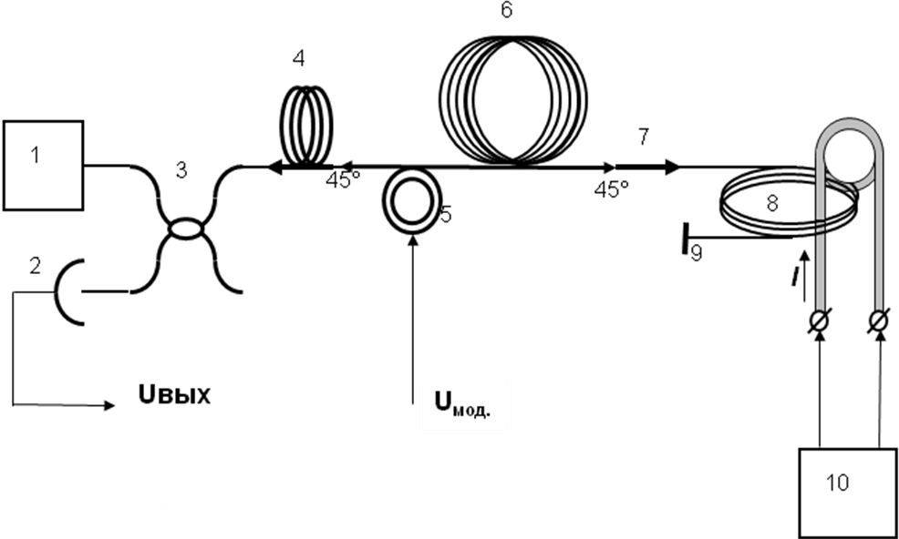
Question 3: Why does the measuring loop measure the current only within the loop itself and remains insensitive to external fields (including the Earth's magnetic field), and why does the positioning of the current busbar relative to the measuring loop not affect the measurement accuracy?
These properties of the measuring loop are determined by a fundamental physical law of nature, expressed by one of Maxwell's equations—the theorem of circulation of the magnetic field strength vector around an arbitrary closed loop. The essence is as follows. In its original form, the expression for the relative phase shift between the working light waves induced by the magnetic field of the measured current looks like this: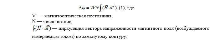 The circulation theorem states that the circulation of the magnetic field vector $\mathbf{H}$ (excited by stationary currents) around an arbitrary closed loop (closure is key) is equal to the sum of those currents $I_j$ that cross the surface bounded by this loop (formula (2), Fig. 3):

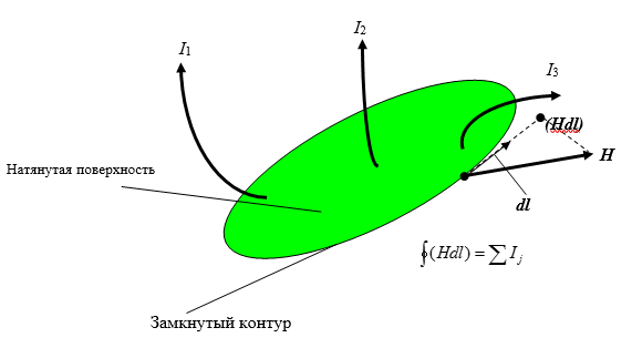
- The signal measured by the current sensor is proportional to the sum of currents crossing the surface bounded by the loop. All geometric characteristics remain within the magnetic field circulation.
- External magnetic fields can be modeled by external currents that do not cross the surface bounded by the loop. Sensitivity to such currents is zero. By modeling the Earth's magnetic field also as an external current, we similarly obtain zero sensitivity to the Earth's magnetic field.
- Moving the current busbar within the loop does not change the conditions of the circulation theorem and, accordingly, does not affect measurement accuracy: the same current still crosses the same surface bounded by the loop. The field strength at the locations of elements $d\vec{I}$, generally speaking, changes when the busbar is displaced; however, the circulation as an integral remains unchanged.
Question 4: What is the property of optical loop closure (i.e., alignment of marks), and how can it be physically explained? What is the essence of the closure, and what will happen if the marks are not aligned with each other, for example, by 10 cm? How close must the fibers being aligned be to each other in the area of the marks, provided that the marks are aligned in a plane, while the turns are spaced 10 cm apart?
A closed fiber loop refers to the complete alignment of the start and end of the sensitive spun fiber along all three coordinates (i.e., axis-axis). Regarding two coordinates, there are no fundamental restrictions on alignment in loops from "Profrotech". For the third coordinate, the limit is the fiber diameter (250 $\mu$m) or the cable diameter (1 cm). In this case, the closure error can be estimated by the value $d_{vol}/L_{cont}$ (rigid head) or $D_{kab}/L_{cont}$ (flexible loop), where $d_{vol}$ is the diameter of the fiber in its protective cladding, $D_{kab}$ is the diameter of the flexible loop cable, and $L_{cont}$ is the length of the loop. In the case of a rigid head with $L_{cont} = 100\text{ m}$ and $d_{wave} = 250\text{ \mu m}$, the closure error is $2.5 \times 10^{-6}$. This value can be used to estimate the residual influence of current bus positioning within the rigid head loop on measurement accuracy. In this case, for a fixed temperature, the residual influence of bus positioning will be $2.5 \times 10^{-6}$ of the measured current value. Within an operating temperature range of $100^\circ\text{C}$, with a loop length of $100\text{ m}$, the gap will change by $1\text{ cm}$. The residual influence of bus positioning will increase to $0.0001$ of the measured current. Such a value is small ($0.01\%$), i.e., it is the level of a good reference transformer. The contribution from external currents will be $0.0001$ of the value of their magnetic fields within the loop area. Using the formula for a flexible loop, one can see that a displacement of $10\text{ cm}$ along one coordinate relative to each other results in a closure error of $0.01$ (at a full loop length of $10\text{ m}$), which can change current measurement readings by up to $1\%$ when positioning the bus within the loop. It is clear that this is unacceptable. The desirable minimum acceptable displacement is $0.001$ of the flexible loop length and does not exceed $0.0001$ for a rigid measurement loop. In reality, the closure of the sensing fiber loop occurs by aligning a fiber phase plate, located at the input of the sensing fiber, with a mirror located at the other end of the same fiber. In the case of a rigid head, such alignment is performed once during manufacturing assembly. Measures are taken to ensure that mechanical impacts do not disrupt the loop's closure. In the case of a flexible loop, loop closure is required during each new installation of the loop at the site. In this case, the criterion for closure is the alignment of marks applied to the outer side of the fiber cable loop. The alignment of these marks is secured by a special and very reliable lock.Read also: The whole truth about optical transformers: part 2
Question 5: What is the physical essence of closing an optical loop? Why is it that specifically upon aligning the marks, the influence of currents from the outside of the fiber disappears, yet sensitivity to currents located inside the closed optical loop remains?
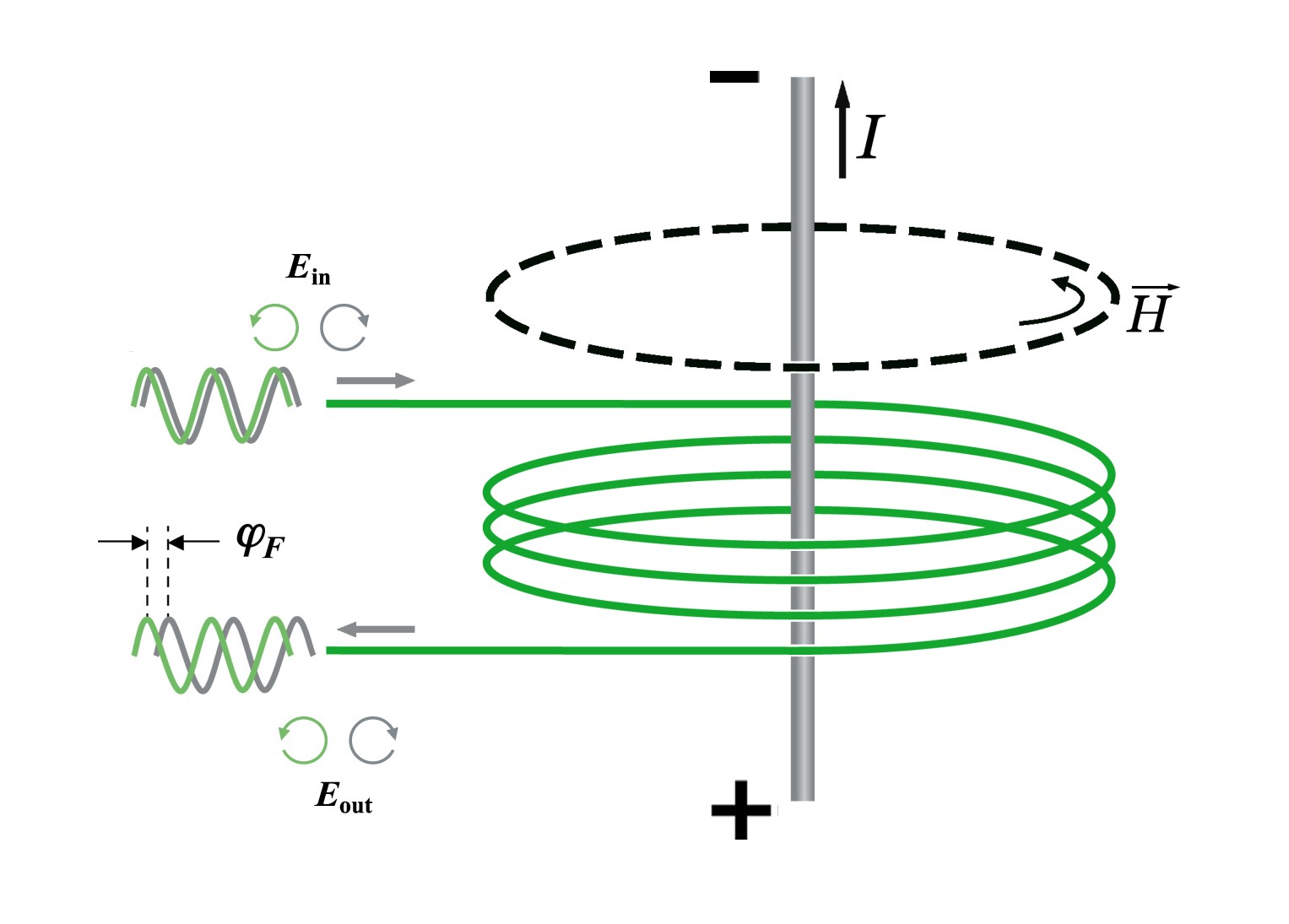
A strict answer to these questions for a closed loop of arbitrary shape is provided by one of Maxwell's equations (the theorem of circulation of the magnetic field vector $\mathbf{H}$ excited by stationary currents). A qualitative explanation can also be provided using the example of a simple circular loop. The phase difference between right and left circularly polarized waves (Faraday shift) when waves pass through an elementary directed section of a waveguide (element) under the influence of a current's magnetic field is determined by the scalar product of the magnetic field vector created by the current and the direction of this fiber element. Hence, the sign of the Faraday shift is determined by the projection of the magnetic field vector created by the current onto the direction of this fiber element. A closed circular loop can be represented as a sum of similar directed elements; in this case, if the busbar is inside the loop, then at any given moment in time, the projection of the magnetic field vector created by the current in the busbar onto a directed element has the same sign for every element of the loop. Consequently, the sign of the Faraday phase shift is the same for any element of the loop. The Faraday shift across the entire loop will be equal to the simple arithmetic sum of the elementary Faraday shifts (the current is sensed inside the loop).For a busbar outside the loop, the situation is different.For half of the elements forming the loop, the projection of the external current's magnetic field vector onto the element is negative, and for the other half of the elements, it is positive. Consequently, one half of the Faraday shifts will have a negative sign, and the other half will be positive. In this case, the total shift around the loop will be equal to the algebraic sum of the elementary shifts, half of which are "plus" and half of which are "minus". A circular loop can be divided into elements such that elementary shifts with opposite signs will be equal in magnitude. As a result, all positive shifts are compensated by negative ones (the external current is not sensed by the closed loop). If the loop is not fully closed, the zero balance is disrupted—and the loop senses the residual external current. If you have any questions about optical transformers, ask them in the comments on the website, in our social networks (vk, fb), or in the Telegram chat; we will certainly find an answer.