 Over the last decade, the term "analog" has become synonymous with "obsolete." On one hand, this sounds offensive and even unfair to reliable equipment that has been tested by years of operation. However, when it comes to increasing the accuracy of measuring instruments and integrating them into a unified monitoring and control network for technological processes, the potential of existing analog equipment is clearly insufficient. One solution is fiber-optic transformers, the operation of which is based on the Faraday effect—an effect discovered at the same time as the law of electromagnetic induction, but which waited for technologies capable of using it effectively to emerge.
Question: Is temperature compensation required for optical current (voltage) transformers to ensure measurement accuracy? In what temperature range is it not required?
First, it is necessary to clarify the terminology by distinguishing between the concepts of basic error and additional error.Indeed, in classical transformer designs, there is a basic transformer error and an entire range of additional errors arising from the presence of harmonics, secondary circuit loading, their mutual influence, as well as temperature. Electronic current and voltage transformers manufactured by JSC Profrotech are transformers with compensated error. For the consumer, this means that the transformers possess only the basic error, while all influencing factors are accounted for in the operation of the electronics and automatically compensated so that throughout the entire operating range of these factors, the transformers remain within the specified accuracy class. Maintaining the specified characteristics is ensured not only by software but also by the design itself. The main features of the measuring part structure will be described below. In the design of electronic current and voltage transformers manufactured by Profrotech, two main parts can be identified:
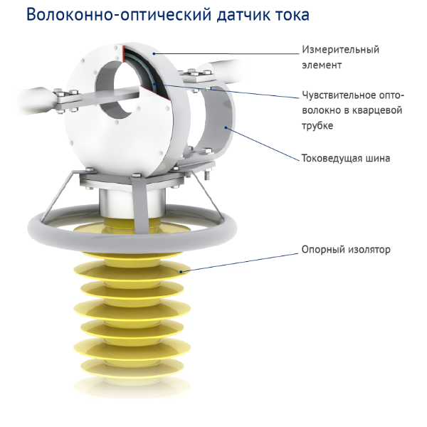
- an external part, where the sensitive optical element is rigidly fixed to a supporting insulation column with a connecting optical cable;
- an internal part, consisting of an electronics unit.
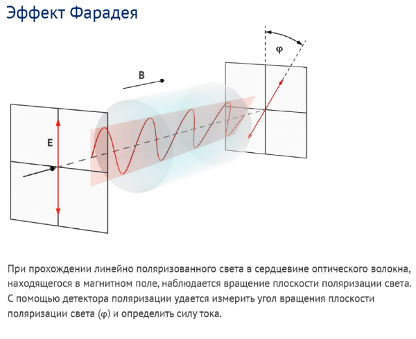
The operation of the optical current transformer is based on a non-contact current measurement method.The method utilizes the magneto-optical Faraday effect and is described in sufficient detail in various sources. Briefly, the essence of the method can be described as follows: two light waves with orthogonal polarization are introduced into a segment of special magneto-sensitive optical fiber (so-called hi-bi spun waveguide) through a fiber analog of a quarter-wave plate, consequently acquiring circular polarization of opposite rotation, which this type of waveguide is capable of maintaining. The introduced light waves are phase-modulated at a fairly high frequency of 40–60 kilohertz (kHz). If there is no current in the conductor around which a loop made of this waveguide is wound, then these light waves propagate at the same speed and arrive at the input of the measurement circuit with zero phase shift. If a current appears in the conductor and a magnetic field is generated around it, the propagation velocity for these light waves will differ due to the Faraday effect. As a result, a relative phase shift occurs in the receiver for the light waves arriving from the sensing fiber, which is proportional to the magnitude of the magnetic field around the conductor and, accordingly, to the magnitude of the current in the conductor. Thus, the task of current measurement is reduced to the precision measurement of the phase shift between the light waves.
The reflective fiber interferometer method is the most mature and stable measurement scheme.To measure these phase shift magnitudes, Profrotech uses the reflective fiber interferometer method in its optical current transformers, as this is the most well-established and stable measurement scheme, providing automatic compensation for most external influences on the measurement path. As previously stated, light waves are modulated by a birefringence modulator; therefore, the interferometer output signal represents a sum of modulation frequency harmonics, where the amplitudes of these harmonics are proportional to the magnitude of the flowing current. This ensures that phase shift calculation is independent of variations in optical scheme parameters (light power at the photodetector, modulation amplitude, etc.). All this allows for high measurement accuracy across a wide range of primary conductor current changes. The special thermostable optical fiber produced by JSC "Profrotech" and used in the measuring elements of optical transformers ensures high stability of properties within a temperature change range of up to 100ºC (the integral spread of readings in this temperature range is approximately 1%), which, given a real temperature range from -60 to +60ºC, provides measurement error in accordance with the requirements for accuracy class 1 measuring instruments. To ensure measurement accuracy in accordance with the requirements of accuracy class 0.2s (extended range in the region of small errors), JSC "Profrotech" devices employ a digital temperature error compensation method for low current values. For this purpose, the current calculation software accounts for the temperature dependence of sensitivity. Every second, in on-line mode, the signal processor reads a signal proportional to the temperature measured by a fiber-optic thermometer located near the main sensing fiber. Based on the read signals, the processor calculates the busbar current value, taking into account the influence of temperature on the sensing element. The reliability of the described compensation is due to the fact that the temperature dependence of sensitivity is fundamental in physical nature and cannot change over time.
All measuring current transformers manufactured by Profrotech undergo test verification in thermal chambers.Measurements are conducted both separately for the sensing elements (in the range from -60 or -40 to +60°C) and for the entire electronic-optical unit (in the range from -10 or +5 to +40°C). In addition to standard industrial thermal chambers for testing sensing elements and electronic-optical units, Profrotech possesses a special climatic chamber capable of conducting tests on high-voltage measuring columns with support insulators for voltage classes up to 220kV with the sensing element installed on them across the full temperature range.
Read also: The whole truth about optical transformers: part 2