В предыдущей публикации [1] мы рассмотрели один из важных и наиболее обсуждаемых коммуникационных протоколов, описанных стандартом МЭК 61850 — протокол GOOSE, — предназначенный для передачи, в первую очередь, дискретных сигналов между устройствами релейной...
In this publication, we will consider the MMS protocol and issues regarding its application in RPA systems.
Strictly speaking, the International Electrotechnical Commission (IEC) 61850 standard does not describe the Manufacturing Message Specification (MMS) protocol. Clause IEC 61850-8-1 describes only the procedure for mapping the data transfer services described by the IEC 61850 standard onto the MMS protocol described by the International Organization for Standardization/International Electrotechnical Commission (ISO/IEC) 9506 standard. To better understand what this means, it is necessary to examine in more detail how the IEC 61850 standard describes abstract communication services and why this was done.
Abstract Data Transfer Services
One of the core ideas embedded in the IEC 61850 standard is its invariance over time. To ensure this, the clauses of the standard sequentially describe conceptual issues regarding data transfer within and between power facilities, then describe the so-called "abstract communication interface," and only at the final stage describe the mapping of abstract models onto data transfer protocols. Thus, conceptual issues and abstract models remain independent of the data transfer technologies used (wired, optical, or radio channels), and therefore will not require revision due to progress in data transfer technology.
The abstract communication interface described by the International Electrotechnical Commission (IEC) 61850-7-2 includes both the description of device models (i.e., standardizing concepts such as "logical device", "logical node", "control block", etc.) and the description of data transmission services. One such service is SendGOOSEMessage; its mapping to the Ethernet protocol was covered in the previous publication. In addition to the specified service, Clause 7-2 describes more than 60 services standardizing the procedure for establishing communication between a client and a server (Associate, Abort, Release), reading the information model (GetServerDirectory, GetLogicalDeviceDirectory, GetLogicalNodeDirectory), reading variable values (GetAllDataValues, GetDataValues, etc.), transmitting variable values as reports (Report), and others. Data transmission in the listed services is carried out using "client-server" technology. For example, a protection relay device can act as the server, while a Supervisory Control and Data Acquisition (SCADA) system acts as the client. Information model reading services allow the client to read the complete information model from the device, i.e., to reconstruct a tree of logical devices, logical nodes, elements, and data attributes. In doing so, the client obtains a full semantic description of the data and its structure. Variable value reading services allow for reading actual data attribute values, for example, via periodic polling. The report service allows for configuring the transmission of specific data when certain conditions are $\text{met}$. One such condition could be a change of some kind related to one or more elements within a dataset. To implement the described abstract data transmission models, the IEC 61850 standard describes the mapping of these abstract models to a specific protocol. For the services under consideration, this protocol is MMS (Manufacturing Message Specification), described by the ISO/IEC 9506 standard.
History of MMS
In 1980, the Manufacturing Message Specification (MMS) protocol was developed for automotive production automation by General Motors. However, the protocol only achieved widespread use after being significantly redesigned by Boeing, after which it became widely adopted in the automotive and aerospace industries and began to be actively used by manufacturers of programmable logic controllers (Siemens, Schneider, Daimler, ABB) [2]. In the 1990s, MMS was standardized as ISO/IEC 9506. Today, a second edition of this standard from 2003 exists.
The tasks addressed during the development of the MMS (Manufacturing Message Specification) protocol were generally similar to the tasks addressed by the IEC (International Electrotechnical Commission) 61850 standard:
Ensuring a standardized data transfer procedure from controllers of various types, regardless of their manufacturer.
Reading and writing data must be performed using standard messages.
MMS Tasks
MMS defines:
a set of standard objects upon which operations are performed, which must exist within the device (e.g., reading and writing variables, event signaling, etc.),
a set of standard messages used for exchange between a client and a server to perform control operations,
a set of encoding rules for these messages (i.e., how values and parameters are mapped to bits and bytes during transmission),
a set of protocols (rules for message exchange between devices).
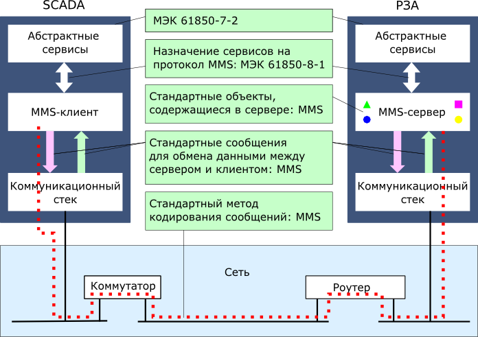
Thus, MMS does not define the application services which, as we have already seen, are defined by the IEC 61850 standard. Furthermore, the MMS protocol itself is not a communication protocol; it only defines the messages that must be transmitted over a specific network. The TCP/IP (Transmission Control Protocol/Internet Protocol) stack is used as the communication protocol in MMS. The general structure of applying the MMS protocol to implement data transfer services in accordance with IEC 61850 is shown in Fig. 1.
Fig. 1. MMS protocol data transfer diagram.
As stated above, the chosen system, which appears quite complex at first glance, ultimately allows for ensuring the immutability of abstract models (and therefore the immutability of the standard and its requirements) on one hand, and utilizing modern communication technologies based on the IP (Internet Protocol) protocol on the other. However, it should be noted that due to its many purposes, the MMS protocol is relatively slow (for example, compared to GOOSE [Generic Object Oriented Substation Event]), therefore its use for real-time applications is impractical.
Execution of Application Data Acquisition Tasks
The primary purpose of the MMS protocol is to implement ICS (Industrial Control System) functions, namely the collection of SCADA (Supervisory Control and Data Acquisition) telemetry and measurements and the transmission of telecontrol commands.
As previously stated, for information collection purposes, the Manufacturing Message Specification (MMS) protocol provides two main capabilities:
data collection using periodic polling of the server(s) by the client;
data transmission to the client by the server in the form of reports (sporadically);
Both these methods are required during the commissioning and operation of an Industrial Control System (ICS); to determine their areas of application, we will examine the operating mechanisms of each in more detail (see Fig. 2).
Data collection by periodic polling of the server by the client
In the first stage, a connection is established between the client and server devices (the "Association" service). The client initiates the connection by addressing the server via its Internet Protocol (IP) address.
Fig. 2. 'Client-server' data transmission mechanism.
In the next stage, the client requests specific data from the server and receives a response containing the requested data from the server. For example, after establishing the connection, the client can request the server's information model using the GetServerDirectory, GetLogicalDeviceDirectory, and GetLogicalNodeDirectory services. The requests will be performed sequentially:
After the GetServerDirectory request, the server will return a list of available logical devices;
Following an individual GetLogicalDeviceDirectory request, for each logical device, the server will return a list of logical nodes within each of the logical devices;
The GetLogicalNodeDirectory request for each individual logical node returns its data objects and attributes.
As a result, the client will read and reconstruct the complete information model of the server device on itself. At this point, the actual attribute values will not yet have been read; that is, the read "tree" will contain only the names of logical devices, logical nodes, data objects, and attributes, but without their values.
In the third stage, the reading of actual values for all data attributes can be performed. During this stage, either all attributes can be read using the GetAllDataValues service, or only individual attributes can be read using the GetDataValues service.
Upon completion of the third stage, the client will fully reconstruct the server information model with all data attribute values. It should be noted that this procedure involves exchanging a fairly large volume of information with a high number of requests and responses, depending on the number of Logical Devices (LD), Logical Nodes (LN), and Data Objects (DO) implemented by the server. This also leads to a significantly high hardware load on the device. These stages may be carried out during the commissioning phase of the Supervisory Control and Data Acquisition (SCADA) system, so that once the client has read the information model, it can access data on the server. However, regular reading of the information model is not required during further system operation. Likewise, it is not advisable to constantly read attribute values via regular polling. Instead, the reporting service — Report — can be used.
Data transfer from server to client in the form of reports
IEC 61850 defines two types of reports — buffered and unbuffered reports. The main difference between a buffered report and an unbuffered report is that when using the former, the generated information will be delivered to the client even if there is no connection between the server and the client at the time the report is ready for issue (for example, if the corresponding communication channel was disrupted). All generated information is accumulated in the device's memory, and its transmission will be performed as soon as the connection between the two devices is restored. The only limitation is the server memory volume allocated for storing reports: if, during the period when the connection was absent, enough events occurred to cause the formation of a large number of reports whose total volume exceeded the allowable server memory capacity, some information may still be lost, and new generated reports will "overwrite" previously formed data in the buffer (however, in this case, the server will notify the client of a buffer overflow and potential data loss via a special attribute of the Control Block (CB)). If a connection between the client and the server is present — both when using buffered and unbuffered reports — data transmission to the client can be immediate upon the occurrence of certain system events (provided that the time interval for event logging is zero).
The second thing that should be noted is that when referring to reports, it implies the monitoring of not all objects and data attributes of the server information model, but only those of interest, which are grouped into so-called "datasets" [3].
A third important point: by using buffered/unbuffered reporting, the server can be configured not only to transmit the entire monitored dataset, but also to transmit only those data objects/attributes that experience certain types of events within a user-defined time interval.
To achieve this, the structure of the transmission control unit for buffered/unbuffered reports provides the capability to define event categories that must be monitored; based on these events, only those objects/data attributes affected by said events will be included in the report. The following event categories are distinguished:
data change (dchg). When this parameter is set, the report will include only those data attributes whose values have changed, or only those data objects whose attribute values have changed.
quality attribute change (qchg). When this parameter is set, the report will include only those quality attributes whose values have changed, or only those data objects whose quality attributes have changed.
data update (dupd). When this parameter is set, the report will include only those data attributes whose values have been updated, or only those data objects whose attribute values have been updated. An update refers, for example, to the periodic calculation of a particular harmonic component and the recording of its new value into the corresponding data attribute. However, even if the value resulting from the calculations in the new period has not changed, the data object or the corresponding data attribute is included in the report.
As previously mentioned, it is also possible to configure the report to transmit the entire monitored dataset. Such transmission can be performed either at the initiative of the server (integrity condition) or at the initiative of the client (general-interrogation). If data formation based on the integrity condition is enabled, the user must also specify the period for data formation by the server. If data formation based on the general-interrogation condition is enabled, the server will generate a report containing all elements of the dataset upon receipt of the corresponding command from the client.
Comparative Analysis of Data Collection via Periodic Polling vs. Reports
The report transmission mechanism offers significant advantages over the periodic polling method ("polling"): it substantially reduces the load on the communication network, reduces the processor load on both the server device and the client device, and ensures rapid delivery of messages regarding events occurring in the system. However, it is important to note that all the benefits of using buffered and unbuffered reports can only be achieved through proper configuration, which, in turn, requires sufficiently high qualification and extensive experience from the personnel performing the equipment commissioning.
Other Services
In addition to the described services, the Manufacturing Message Specification (MMS) protocol also supports equipment control models, event log generation and transmission, as well as file transfers, which allows for the transmission of, for example, fault waveform files. These specified services require separate consideration.
Conclusions
The Manufacturing Message Specification (MMS) protocol is one of the protocols to which abstract services described by the International Electrotechnical Commission (IEC) 61850-7-2 standard can be mapped. At the same time, the emergence of new protocols will not affect the models described by the standard, thereby ensuring the stability of the standard over time.
IEC 61850-8-1 is used for mapping models and services to the MMS protocol.
The MMS protocol provides various mechanisms for reading data from devices, including on-demand data reading and data transmission in the form of reports from the server to the client. Depending on the task being solved, the correct data transmission mechanism must be selected and appropriately configured, which will allow for the efficient application of the entire set of IEC 61850 communication protocols at a power facility.
References
1. Anoshin A.O., Golovin A.V. IEC 61850 Standard. Generic Object Oriented Substation Event (GOOSE) Protocol // Elektrotekhnika News. 2012. No. 6 (78).
2. MMS. Presentation by Prof. Dr. H. Kirrmann, ABB Research Center, Baden, Switzerland.
3. Anoshin A.O., Golovin A.V. IEC 61850 Standard. Device Information Model // Elektrotekhnika News. 2012. No. 5 (77).